Sequential Logic Operation & Its Components Activity
The manner of operating a machine or equipment or a production system by feeding the steps into a particular order for safe start-up, operation, annunciation, and shutdown as per the requirements of the process is called Sequential Logic Operation.
The manner of operating a machine or equipment or a production system by feeding the steps into a particular order for safe start-up, operation, annunciation, and shutdown as per the requirements of the process is called Sequential Logic Operation.
The Instrumentation needed to achieve it is called Sequential Logic Instrumentation.
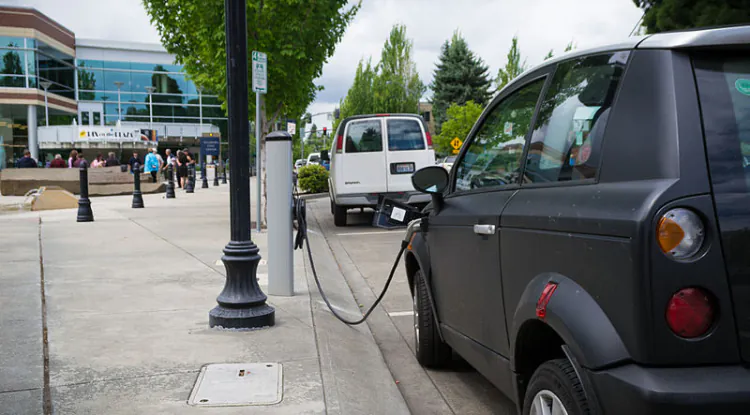
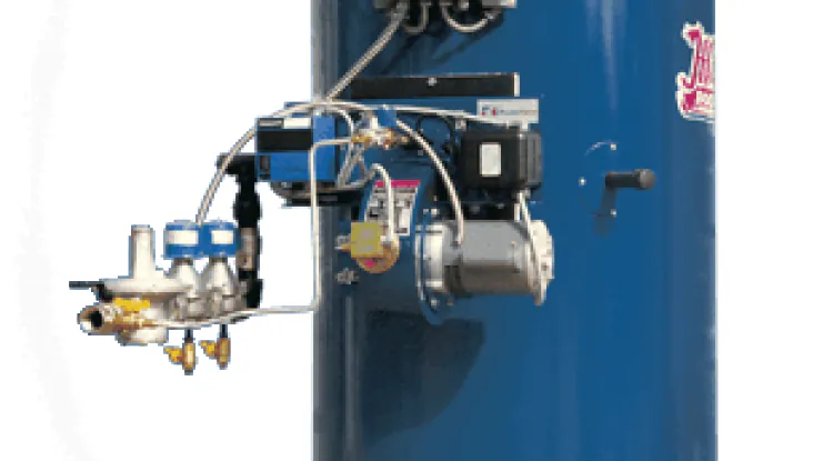
Sequential control improves the quality of control as well as the safety of the machine and plant. An example will make it clear. For the smooth running of a compressor, lubrication is necessary. A lube oil pump supplies oil to the bearing of the compressor to protect it from overheating. To save the compressor, the lube oil pump is to be started first before starting the compressor. The compressor and the pump can be interlocked (electrical) so that, without starting the lube oil pump, the operator can not start the compressor.
This type of protection system of a machine, by proper instrumentation, is called Interlocking.
There are two types of Sequence System:
- By Electromagnetic Relay
- By Programmable Logic Controller (PLC)
In the conventional sequence system, electromagnetic or solid state relays, timers, counters, etc, are used as switching elements.
On the other hand, in the computerized control system, electromagnetic or solid-state relays, timers, counters, etc, are replaced by microprocessor-based programmable logic. Controller (PLC)
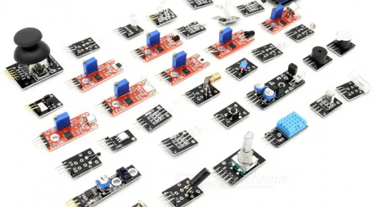
Components of the Conventional Sequence System
The main components of a conventional sequence system are switches, relays, timers, counters, solenoid valves, etc.
Related: Introduction to Process Instrumentation
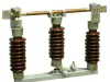
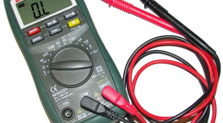
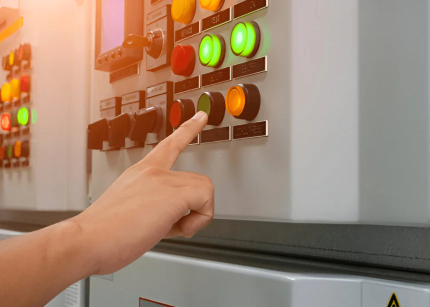
Switch
The electric switch is a device that is used for making, breaking, or rerouting connections in an electrical circuit to operate the load. The switching is accomplished by the opening or closing of two metal surfaces.
Types of switches: Mainly, switches are of three types:
- Momentary Action Switch
- Maintained Action Switch
- Push-push Action Switch
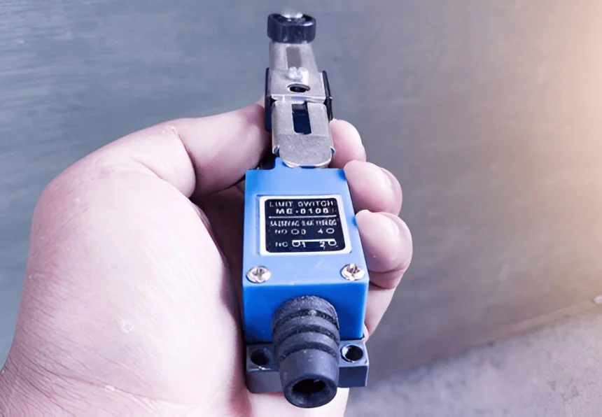
Momentary Action Switch: When actuated power is applied to the switch, it changes its position, but if the power is withdrawn, the switching position will be returned to the Previous position. This type of switch is called the momentary contact switch.
Example: Push button switch, Limit switch, Level switch, pressure switch, etc.
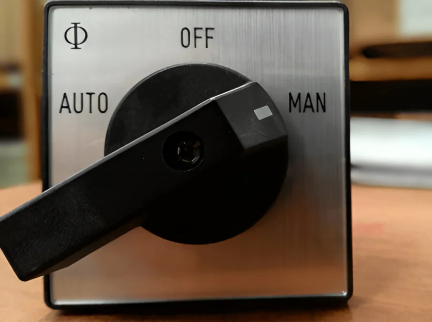
Maintained Action Switch: When the actuated power is applied to the switch, it changes its position, but if the power is withdrawn, the switching position will remain unchanged. This type of switch is called the maintained contact switch.
Example: Normal on-off switch, changeover switch, toggle switch, slide switch, etc.
Push-push Action Switch: When the actuated power is applied to the switch, it changes its position, but if the power is withdrawn, the switching position will remain unchanged. If the power is applied, the switching position will be returned to the previous position. This type of switch is called a push-push action switch.
Example: TV Switch, Industrial ON-OFF Switch.
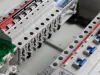
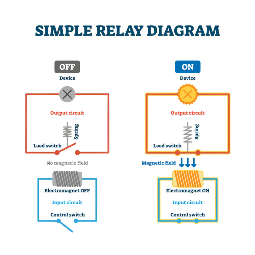
Relay
A relay is an electrically controlled device that can open or close several contact paths simultaneously when its coil is energized by electric power. By using a low level of control energy in the relays, it is possible to switch high power levels and actuate several contacts at the same time.
Functional components: Electro-magnetic relays consist of the following.
Coil, Iron Core, Armature, Contacts, Spring.
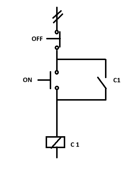
Self-hold System Relay
Concept on NO and NC Contact of Relay: If the contact of a switch or relay remains closed under an actuated force-free condition, the contact is called an NC contact. Actuated force may be mechanical, electrical, hydraulic, or any other means. On the other hand, if the contact of a switch or relay remains open under an actuated force-free condition, the contact is called an NO contact. A relay may have several sets of NO and NC contacts. In every set of contacts, there is a common (COM) terminal.
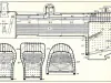
Sequential Operation of a Typical Level Control Loop
We want to control the liquid level of a tank (as shown in the following figure) in such a way that when the liquid level goes below 20% level low alarm appears and the pump starts by level switch low (LSL) and continues to run till the high level appears. When the level of liquid reaches 80%, level high-level alarm appears and the pump stops automatically by the high-level switch (LSH). It remains stopped until the level alarm appears. For the above automatic operation, the selector switch must be positioned in AUTO mode. The pump should have the facility of starting and stopping manually at any time. In that case, the selector switch must be positioned in MAN mode.
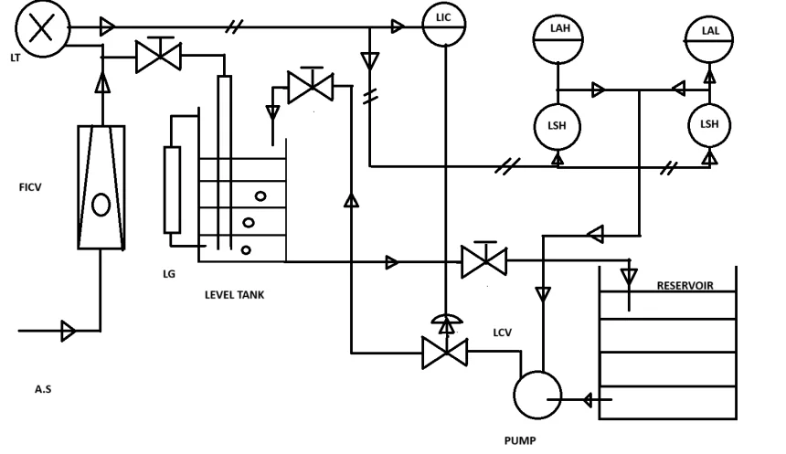
P & I Diagram of Control Loop.