Basic of Controller & Control Loop
A controller is an instrument that receives an input signal from the transducer or transmitter as measured value (MV), compares this measured value with the desired value (SV), and produces an output signal for the correcting element/ control value.
A controller is an instrument that receives an input signal from the transducer or transmitter as a measured value (MV), compares this measured value with the desired value (SV), and produces an output signal for the correcting element/ control value.
Types of Controllers: Controllers can be classified in many different ways.
Based on Auxiliary Power
- a) Pneumatic Controller,
- b) Electronic Controller
Based on the Working Principle
- a) On-off controller
- b) Proportional controller
- c) Proportional plus Integral (PI) controller
- d) Proportional plus Derivative (PD) controller
- e) Proportional plus integral plus Derivative (PID) controller
Proportional (P) Controller:
In the proportional controller, the output variation is proportional to the deviation between the measured value (MV) and the desired value (SV). The figure shown below is a schematic diagram of a pneumatic proportional controller.
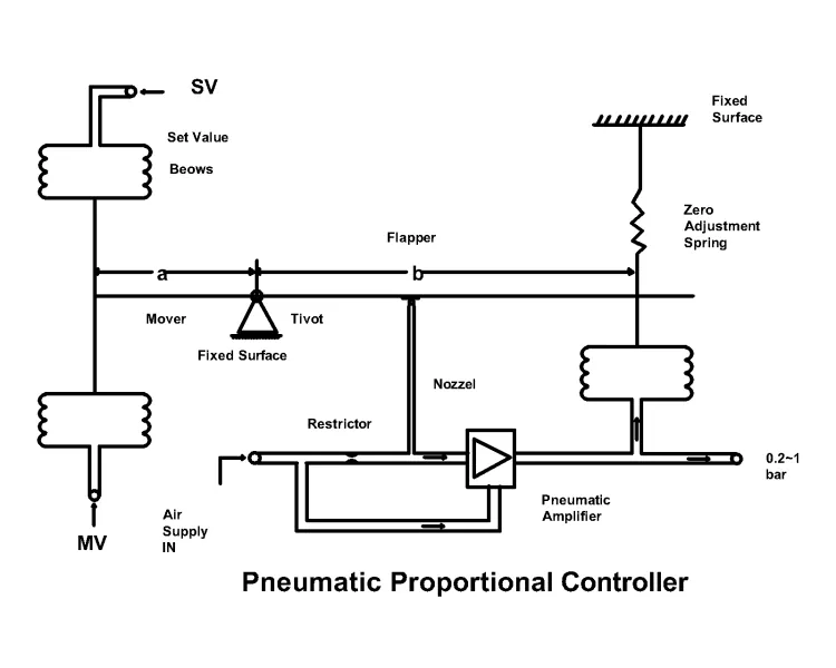
At a balanced condition, the resultant of the moments should be zero. So, taking a moment around the pivot (Clockwise +ve), we get
a. Pm - a. Ps + b. Pf - b. Po = 0
Or Po = a/b (Pm - Ps) + Pf
Or Po = k.e + 0.6 bar, Where Pf = load spring pressure = 0.6 bar
& K = 1/ PB = 100 / (PB in %)
So the output equation can be written as Po = k.e + 0.6 bar

Offset (Closed-Loop)
The Disadvantage of the Proportional Controller: Remains offset.
Proportional + Integral (PI) Controller:
In the proportional + Integral (PI) controller, a reset bellows with a variable restrictor is introduced which replaces the load spring. It is capable of making offset zero by integral action.
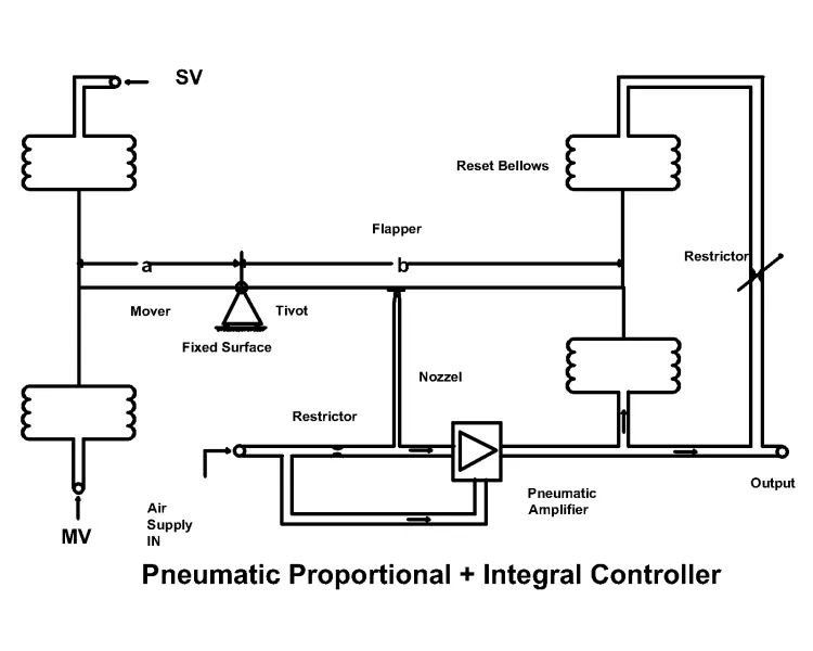
Features of PI Controller
- The load spring is replaced by a reset bellows with a variable restrictor
- The variable restrictor is a needle valve, and the dial is graduated in terms of time
- The output of the PI controller, Po = K.e + K / Ti ∫ e dt + Ko Bar
- Because of integral action, the output continues to change until there existsa deviation
- Ultimatel,y there is no offset
Different Conditions of Reset Restrictor:
- Restrictor fully closed (p controller)
- Restrictor fully open (ON-OFF controller)
- Restrictor partially open (PI controller)
Reset / Integral Time:
Reset or integral time is the time required to change the output of the controller due to integral action which is equal to the same amount of change due to the proportional action.
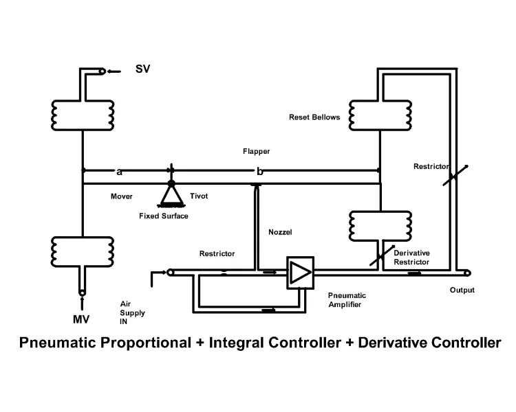
Proportional + Integral + Derivative Controller (PID):
Features of PI D Controller
- Variable restrictor is introduced with the feedback below
- Restrictor dial is graduated in terms of time
- The output of PID controller, Po = K.e + k / Ti ∫ e dt + K Td. de/dt + Ko Bar
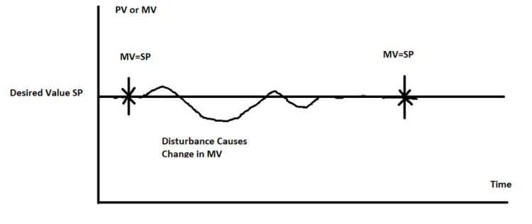
Typical Response of a PID Controller to a Change in Measured Value
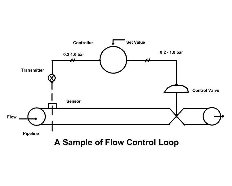
Control Loop: The arrangement of instruments connected with each other to control a physical variable to the desired value is called a control loop.
Related: Introduction to Distributed Control System (DCS)
Elements of Control Loop:
- Process: a variable that has to be controlled
- Measuring system: measures the physical variable
- Transmitter: The transmitter measured the signal to the controller
- Controller: This generates the control command according to the desired value
- Final control element: Which carried out the control command
- Connecting tubes and pipes: which passes the signals
Types of Control:
1. Feedback Control ( closed-loop control)
2. Feedback Control (open-loop control)
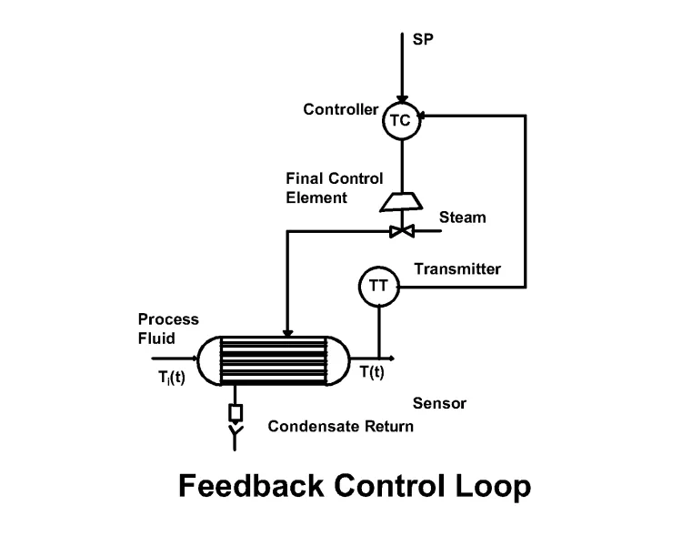
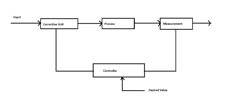
Block Diagram of Feedback Control Loop
Temperature can be controlled according to the above control loop. However, there is a fluctuation in the measured value because the temperature-sensing response time is high.
Cascade Control Loop:
In cascade control, two control loops are coupled to each other. The output of one controller is the set point for another controller. The cascade control loop is often called “Mater-Slave” control.
The cascade control loop consists of the following:
- Two measuring systems /transmitters
- These two controllers, one is the master and the other is the slave
- One control valve
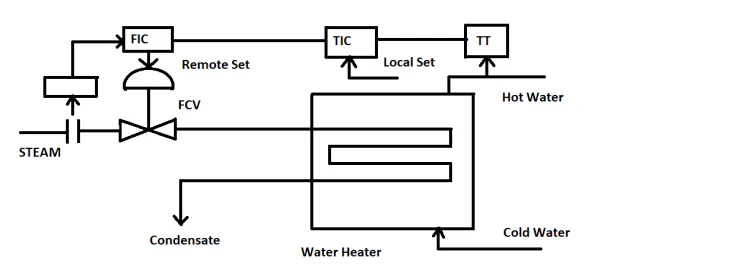
Block Diagram of Cascade Control Loop
Operation: For a particular set value of the master controller TIC (PID controller), if the temperature of the hot water increases, the output of TIC is fed as the remote set-point of FIC, also increasing, causing the control valve to close. At the same time, the steam flow will decrease and the salve controller FIC will get a sense through FT. Ultimately, the temperature will decrease and be controlled at the set value. During the decrease in hot water temperature, the reverse operation will happen.