Introduction to Distributed Control System (DCS)
The Distributed Control System (DCS) is one kind of computer control system, in which the control is distributed to computer modules containing one or more microprocessor-based controllers & each controller has capabilities to control several instrument loops.
The distributed control system is one kind of computer control system, in which the control is distributed to computer modules containing one or more microprocessor-based controllers & each controller has capabilities to control several instrument loops.
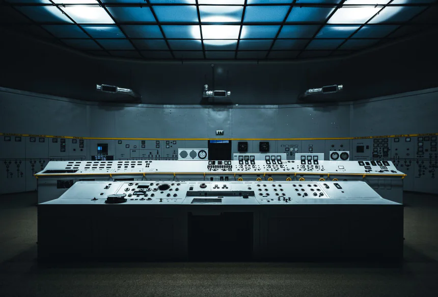
Every controllers or computer modules are connected together by a single high-speed data link, called a data highway, which permits communications between each of the microprocessor-based modules and the central control console. Control console basically consists with CRT for process status looking, a two/three-level keyboard for process operation & system configuration, a Printer for process status hardcopy representation, and also its own memory to store data in its microprocessors to process data, and its own communications interface for being tied to the data highway etc.
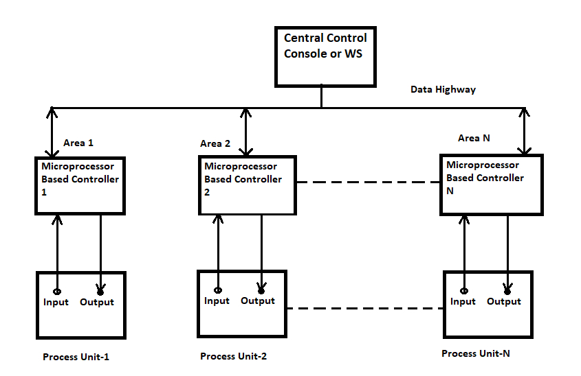
Basic Schematic Diagram of a Distributed Control System (DCS)
DCS is a Very Broad Term Used in a Variety of Industries to Monitor and Control Different Processes. Some examples are below,
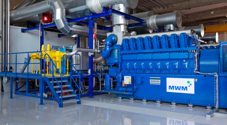
- Electrical Power Grids and Electrical Generation Plants
- Environmental Control Systems
- Traffic Signals
- Water Management Systems
- Oil Refining Plants
- Chemical Plants
- Pharmaceutical Manufacturing
- Steel Manufacturing
- The system is reliable & speedy
- If any microprocessor fails, only one portion of the overall system will be out of control, not the whole assembly.
- Similarly, if the station fails, the whole field units should be alive.
- It is much easier to make software changes to the distributed system.
- The availability of color CRT-based operator control centers provides more information and guidance to the operator for their actions.
- Control rooms are simplified, as all information is available on the CRT.
- Extensive diagnostic schemes are available.
- Redundancy and fail-safe techniques incorporated permit high reliability and availability of the system.
Today we will talk about a basic DCS Operation System Name "Plantscape System" for a Example Process Plant.
Plantscape System (Windows-Based DCS):
Plantscape is one kind of distributed control system for a process plant. The PlantScape server, stations & operator interface provide an operator window to the plant or process. With plantscape, the user only needs to configure the system, allowing the user to concentrate more on the application. There are three different types of plantscape systems available:
- Plantscape Vista: Use on small systems using Honeywell UDC controller and similar.
- Plantscape SCADA: For use of the SCADA systems using a wide variety of Honeywell and 3rd party controllers & PLCs.
- Plantscape Process: Same as plantscape SCADA, but also fully integrated with the plantscape hybrid controller ( OUR Example Process Plant)
Plantscape System Hardware Consists of:
Process Units:
- Process equipment/Instrument
- UMC 800 (Microprocessor-based multiloop controller)
- Networking devices
Management Units:
- Plantscape server
- Plantscape workstation
- Networking devices
- Printer etc
Functional Block Diagram of PlantScape System:
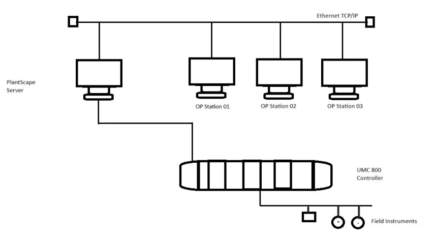
Process equipment/instruments: Like conventional control systems, DCS also has field or process equipment or instruments as flow meters, D/P transmitter, T/C, RTD, Analyzers, control valves, recorders, pumps, SV, Limit SW, Motor, Smart transmitters, PLCs, etc
Related: Basic of Controller & Control Loop
UMC 800 Controller: The universal multi-loop controller (UMC 800) is a modular controller designed to address the analog and digital control requirements of small unit processes. With up to 16 analog control loops, four set point programmers, and an extensive assortment of analog and digital control algorithms, the UMC800 is an ideal control solution for furnaces, environmental chambers, ovens, reactors, cookers, freeze dryers, extruders, and other processes with similar control requirements.
The operator interface uses a color graphic LCD display to provide a variety of display presentations for viewing control loops, set point programs, and other analog and digital status. A separate control builder configuration software program is used for system configuration that operates on a Windows 95/98 or NT-based PC.
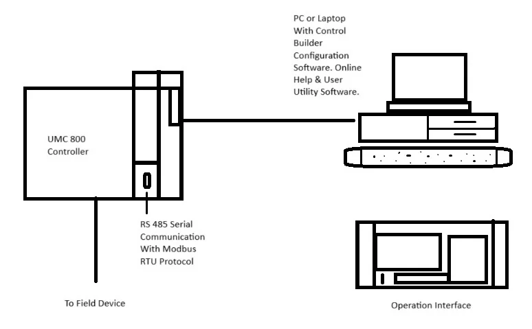
UMC 800 Controller
PlantScape Server: The computer on which the PlantScape database software runs. The plantscape server provides an operator's window to the plant or process. The major functions provided by the PlantScape Server are:
- Fully integrated with the plant scape hybrid controller.
- Interface to other Honeywell and 3rd party controllers.
- Distributed server architecture enabling data sharing with other PlantScape.
- Acquisition and control algorithms.
- Historical data collection display.
- Reports.
- PC based operator stations.
- Alarm and event management.
Station: The main operator interface to the plantscape. Stations may run on either a remote computer through a serial or LAN link or on the server computer. When a station is running on the plantscape server computer, it is often referred to as a server station. When it is running on a machine other than the server, it is often referred to as an operator station.
Networking: Computers are usually connected together on a network so that the applications (programs) running in each of the computers are able to pass information to each other. The network hardware,s that plantscape uses is Ethernet, and different protocols are used to transfer information to different stations. The plantscape server uses TCP/IP to trans data to connected stations.
Data Storage Philosophy of DCS
Process Data Storage Media: In this system, the data may be saved on a hard disk, or ZIP drive floppy disk, or a writable CD in the CD-ROM drive. By using these disk drives, we can upload or download the system programs & also store them on that disk. This type of storage device is called auxiliary memory. It is also possible to print the start-up log, shutdown log, and previous events from the above media. As for example, operator message, process alarms, system status, etc.
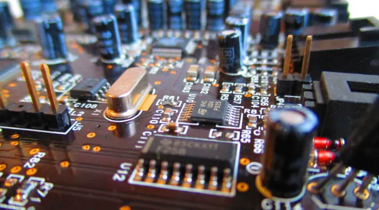
Semiconductor Memory: A semiconductor is a microscopic component, such as a transistor or diode. In semiconductor storage, thousands of miniature components are combined on a tiny silicon chip. Metal oxide semiconductor (MOS), Complementary MOS (CMOS), and bipolar semiconductors are the major technologies used in semiconductor memories. Semiconductor storage devices are called integrated circuits (IC), since all the storage components & address decoding are integrated on a single chip. Semiconductor storage is available in different types. They are RAMs, ROMs, PROMs, EPROMS, EEPROMs & dynamic RAMs. The most commonly used & cheap semiconductor storage is battery backup RAM (because they are volatile). RAM is a high-memory capacity & used as working memory. On the other hand, ROMs are used in applications in which the programs or data in ROM are not to be changed (because they are non-volatile). EPROMs are mostly used.
REDUNDANCY SYSTEM
Many manufacturers, depending on process emergencies, offer systems with built-in back-up features so that the failure of one part of the DCS does not affect the system's performance at all. There are several ways of providing these features. Partly or wholly part may be backed up or redundant. Redundant mode may be selected through by manual switch or an automatic system. Below shows a typical redundancy system.
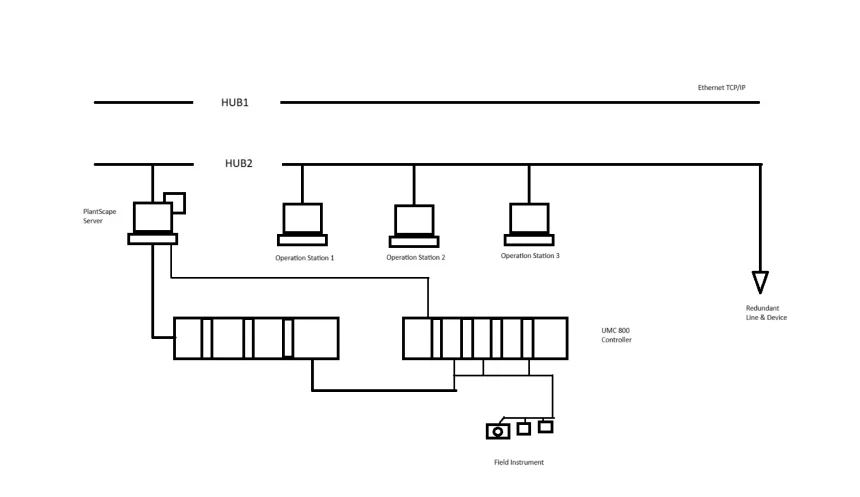
Redundance System
Related: What is Control Valve and its Classifications
Diagnostics & Troubleshooting
Different types of problems arise during plant running or conditions. The DCS system has facilities to monitor & find out the messages/events through different menus/ icons on the DCS screen. These menu/icons may be:
Alarm Icons: When any event occurs due to process abnormality or system fault, then the Alarm icon will be flashed with Red color & audio sound. By selecting this Alarm icon, we can get the details causes & identifications of problems.
Logic or Interlock Diagram Menu: Logical or on /off events can be identified through this menu, so that where is the problem so start/ stop a device.
Monitor Mode in Process Configuration Menu: In this mode, we can observe the on /off status of input/output devices & other parameters. To test the devices, we can force on/ off of devices for loop/logic checking.
Software of the PlantScape System: The PlantScape server software is divided into functional subsystems. Each subsystem consists of tasks of task groups to execute and manage data flow. All task groups have access to the server's real-time database. The database is located solely in the plantscape server and is not distributed.
Pilot Plant Areas: Now consider our Example Process Plant Where, DCS pilot plant & which is configured as AREA-0.1. Under AREA-01, there are 3 units. Unit 01 is the pressure control loop (process-p300), unit 02 is the flow control loop (process-P800) & unit 03 is the furnace temperature control loop (process-T1100). Again, there may be sub-units under every unit.
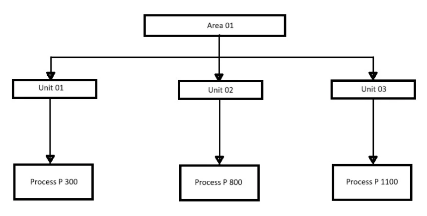
Areas
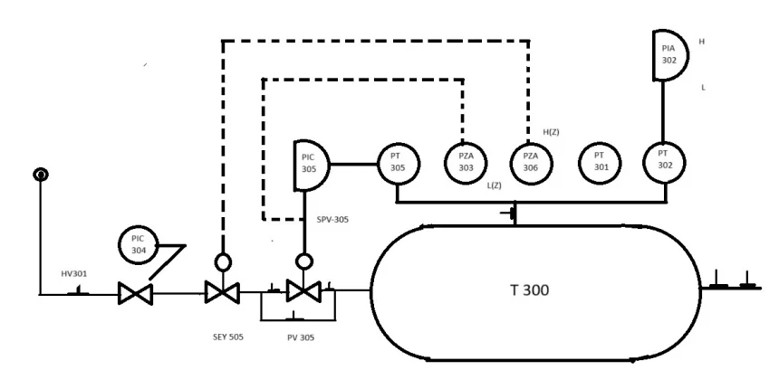
P & I Diagram For Pressure Control Loop