What is Turbine and its Classification With Components
What is a Steam & GAS Turbine, Classification, Components with Advantages of GAS Turbine Over Steam Turbine.
A Turbine is a machine that converts the pressure, velocity, and heat energy, i.e., decreases the head or energy level of the working fluids passing through it, to the rotational energy, i.e., mechanical energy of the turbine rotor is called turbine. This mechanical energy of the turbine is utilized to drive different turbo machinery like a generator, a pump, a compressor, etc. Depending on the working fluid turbine may be classified as follows:
- Steam Turbine
- Gas Turbine
- Water Turbine
- Wind Mill
The working fluid causes to fall in pressure in a passage or nozzle. Due to this fall in pressure, a certain amount of heat energy is converted into mechanical kinetic energy, and the working fluid is set in motion with a greater velocity. The rapidly moving particles of the fluid (water, steam, or gas) enter into the moving parts of the turbine and here suffer a change in direction of motion, which gives rise to a change of momentum and therefore to a force. This constitutes the driving force of the machine.
Steam Turbine
The Steam turbine is a steady-flow machine in which steam enters a nozzle and expands to a lower pressure. In so doing, the steam jet develops a high velocity. Part of the kinetic energy of this jet can be delivered to the blades of the turbine in the same manner that a jet of water can deliver energy water to the buckets of a water wheel.
The Major Components of a Steam Turbine
- Rotor
- Moving blade
- Nozzle, stator blade, guide blade
- Diaphragm/Blade holder
- Casing (upper half & lower half)
- Bearing (journal bearing &thrust bearing)
- Main stop valve/Emergency stop valve/throttle valve
- Governing valve or control valve
- Extraction/Admission control valve
- Gland seal, stage seal, blade-tip seal
- Oil guard or oil deflector
Description of Functional Components:
Casing:
Bearing Housing: The bearing housing is supported on a pedestal at shaft height, independently of the turbine casing. The relative location of the pedestal to the outer casing is conveniently adjusted by means of screw adjusting device. The thermal expansion of the turbine takes place freely on the guide-way.
Bearing:
Nozzle:
Guide Blade:
- Conversion of potential into kinetic energy (for reaction turbine)
Moving Blade:
Shroud:
- Shroud supports the blades and also prevents the steam from being cast off radially
Rotor Chamber:
- The space within which the rotor runs is called the rotor chamber
- Steam seal
- Glade seal
- Blade tip seal
- Stage seal
Classification of Steam Turbine:
A) According to the Mode of Action
- Impulse Turbine
- Reaction Turbine
B) According to the Direction of Steam Flow
- Axial Turbine
- Radial Turbine
C) According to the Pressure of the Working Fluid
- High Pressure Turbine
- Medium Pressure Turbine
- Low-Pressure Turbine
D) According to the Number of Stages
- Single Stage
- Multi Stage
E) According to Steam Exhaust/Steam in & out Condition
- Condensing Turbine
- Back-pressure Turbine
- Extraction Turbine: i) Extraction-Backpressure, ii) Turbine
- Admission-Condensing Turbine
Condensing Turbine: Where all the exhaust steam is passed to a condenser. This type is the most common
Backpressure Turbine: Which has no condenser. The exhaust steam, at an appropriate pressure, is generally used for the heating process.
Extraction Turbine: In this case, steam is extracted for process work at one or more stages of the expansion, the remainder being expanded down to condenser pressure.
Mixed Pressure Turbine: In which steam is supplied from two or more sources at different pressures.
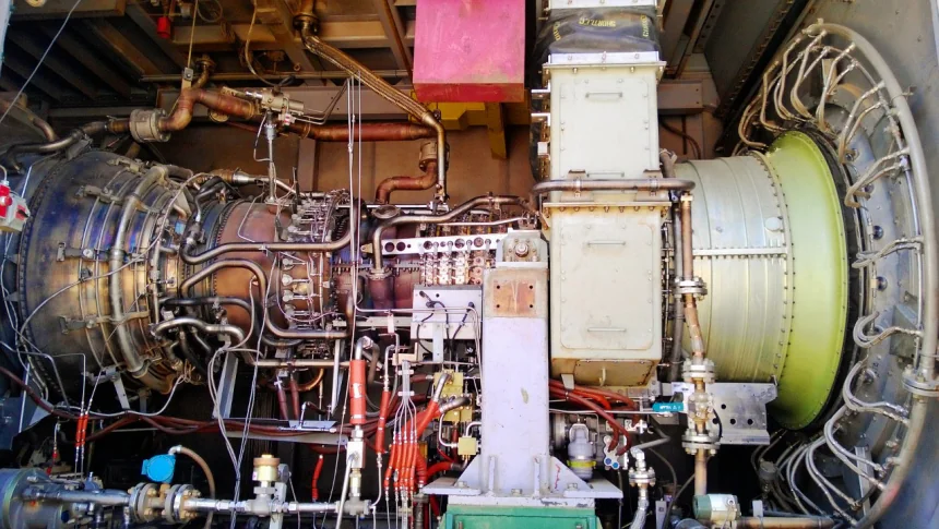
Gas Turbines
The simple gas turbine consists of an air compressor, a combustor, a turbine, and several auxiliaries as influenced by weight-power ratio and speed characteristics. The auxiliaries must provide for lubrication, speed control, fuel supply, and starting.
Several practical limitations are encountered in gas turbine operation; such limitations largely determine the maximum performance that can be obtained. Among these are blade temperature, blade speed, compressor efficiency, turbine efficiency, and heat transfer.
In the operation of the simple gas turbine, compressed air is delivered to the combustor where fuel is supplied in steady flow and a continuous flame is maintained, the original ignition usually being made by means of a spark. The air, heated in the combustor, expands through nozzles and develops a high velocity. Some of the kinetic energy of the air stream is delivered to the blades of the turbine. Part of this energy is used to drive the compressor, and the remainder is available for shaft work.
The Major Components of a GAS Turbine
- Rotor (Compressor & Turbine )
- Inlet Guide Vane (IGV)
- Stator Blade (Compressor & Turbine)
- Moving Blade (Compressor & Turbine)
- Diaphragm/Blade Holder
- Casing (Inner Casing & Outer Casing )
- Bearing
- Combustor
- Gland Seal, Stage Seal, Blade-tip Seal
- Oil Guard or Oil Deflector
- Base Plate
- Pedesta
Classification of GAS Turbine
a) According to the Path of Working Substance
- Open Cycle GAS Turbine
- Closed Cycle GAS Turbine
- Semi-Closed Cycle GAS Turbine
b) According to the Process of Heat Absorption
- Constant Pressure GAS Turbine
- Constant Volume GAS Turbine
In the open system, the products of combustion flow with the air stream through the turbine. A high percentage of excess air (3oo to 600 percent) is necessary in order to dilute the combustion products to a temperature that the turbine wheel can withstand, 1200 to 1800 0F.
In the closed system, the products of combustion do not pass through the turbine but are directed through a heat exchanger. The gases passing through the turbine are made to operate in a closed circuit, being consecutively compressed, heated, expanded, and cooled. The closed system permits the use of fuel of any type in the combustor, but a heat exchanger is required. Therefore, the closed system is limited.
Advantages of the GAS Turbine Over the Steam Turbine
- More Compact
- Fewer Auxiliaries
- No Condenser Maintenance
- No Water Requirements