Electrical Busbar Classification, Management With Calculation
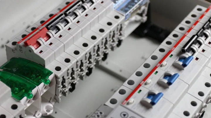
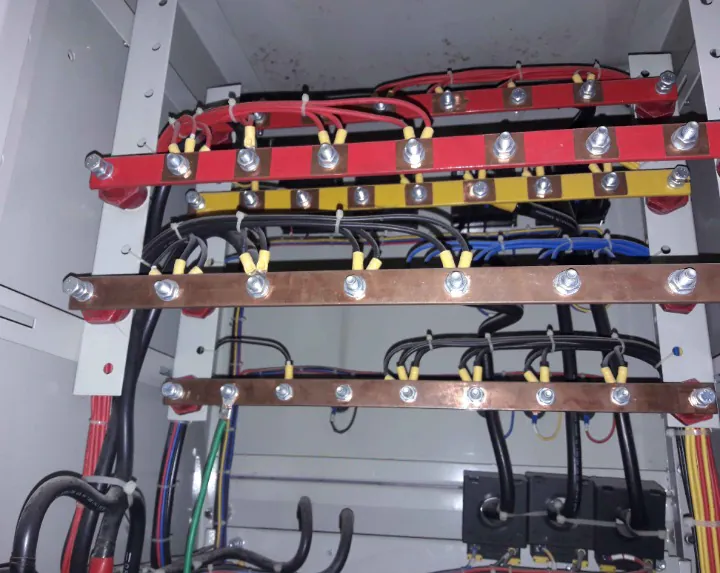
An electrical Busbar is a modern way to transfer electricity by using Copper and Aluminum Plates which are covered by a protective insulating cover or not. Generally, we drill holes on the Busbar and then we bolt cable lugs with it.
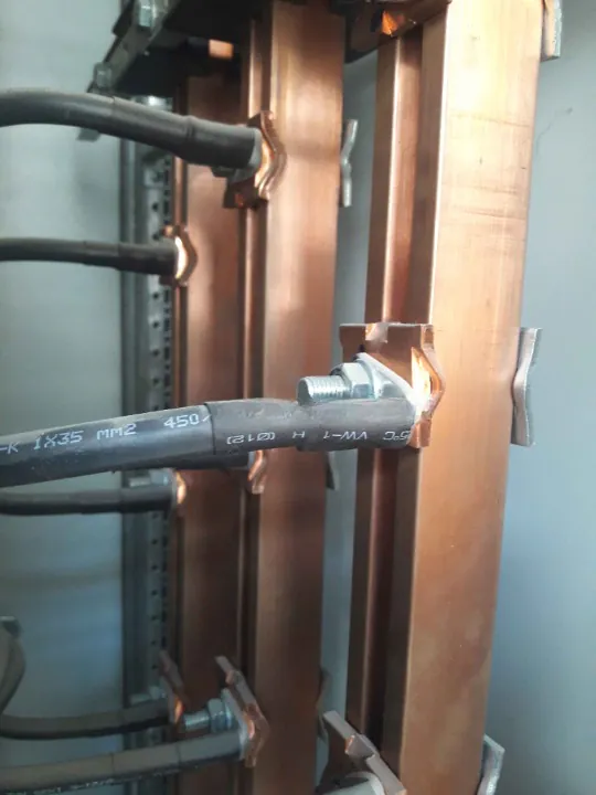
We use a network of cables with different voltage ratings to transfer electricity through the circuit. Copper and Aluminum are the most popular cable conductors. An electrical Busbar is a modern way to transfer electricity by using Copper and Aluminum Plates, which are covered by a protective insulating cover or not. Generally, we drill holes on the Busbar and then we bolt cable lugs to it.
Usages of Busbar:
Busbars are frequently used inside a panel board and as a main power carrier from a power transformer and generator. Now, the reason behind the use of Busbar is as follows,
- We can easily transfer electricity to different loads.
- If you are using a Busbar, then you can keep one side of the bar active when you are performing maintenance to a load side.
- If there is any glitch in the system then you can deactivate that part from the active system.
Feature of Busbar:
- The conductor you use as a Busbar must have less resistance value.
- If there is any change in temperature due to load demand then the conductor material resistance value will not change.
- Required insulation material space between two or more conductors must be available.
- Busbar metal conductors should have high mechanical strength.
- If shortly, the output load limit increases then it should have the capacity to adjust with the required load to a specific limit.
- Future extension options should be available.
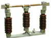
Classification of Busbar:
Generally, Busbar classification depends on its usage, like where to use it, load type, and others. Here are some different types of busbars,
- Outdoor Busbar.
- Indoor Busbar.
- Enclosed Busbar.
- Open Busbar.
- Isolated Phase Busbar.
- Gas-Pressurized Insulated Busbar.
- Oil Sinking Busbar.
Busbar Management:
Busbar management is as follows,
- Single Busbar.
- Sectional Single Busbar.
- Sectional Double Busbar.
- Double Busbar with Single Breaker System.
- Ring Busbar.
Now come to the selection of a Busbar size. There are some rules and guides that need to be maintained during the designing or selecting a Busbar and those are,
- According to the plant efficiency, the Busbar should have an option to activate the entire Busbar or half of the Busbar.
- The amount of load that needs to be carried.
- Primary installation cost.
- Operation and maintenance costs.
- Future extension option.
- Busbar size selection.
- A safe place to install.
Busbar Size Calculation:
Generally, a Busbar's size depends on the total ampere of current that it needs to carry. If carrying current is small, then its size will be small, and if it is carrying a high amount of current, then its size will be large. When you are calculating the size of a Busbar then you have to keep in mind the height and thickness of the conductor plate that you use. The calculation of the Busbar will be denoted by a millimeter.
Example of Busbar Calculation: Let’s consider we have a 600KVA power transformer or a generator which have 400V as the line voltage. Now total ampere we can get
I=(1000×600)/(√3×400)=866A
Now we have to add a minimum of 25% extra ampere for safety reasons with 866A. You can add more percent according to your demand with future extensions. Then our total ampere will be 1082A.
Now Basbar calculation formula is
2A=1mm2
1A=1/2mm2
1082A=541mm2
Please note that 2 (1.7~2) is the density of copper. If you go with 1.7 then 25% extra ampere will not be required. Now we have to reach 541mm2 by multiplying the height and thickness of copper, like 108×5=540A. If this size of the copper plate is not available in the market, then take the nearest size, but the upper size.
Some Common Busbar Sizes:
Here are some most common Busbar sizes,
19.05mm×6.35mm = 100A
25.40mm×6.50mm = 250A
30mm×10mm = 400A
40mm×10mm = 600A
44.45mm×12.70mm = 800A
50.80mm×12.70mm = 1000A
2×63.5mm×9.525mm = 1600A
2×80mm×10mm = 2500A
Now, if you like this post, then share it with your friends. Thanks!